Showing posts with label Kawartha Lakes Railway. Show all posts

Friday, July 24, 2020

Pontypool / Cargill Construction

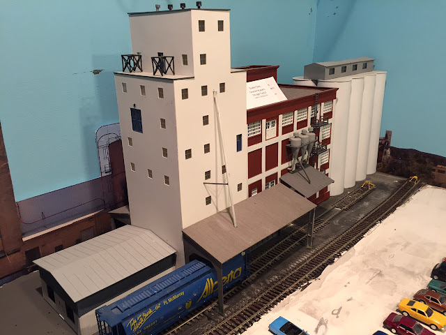
When I decided to change the layout to install a new yard, I ripped out a previous corner that was basically finished with scenery, which is always difficult to do. However, I rationalized that it was basically a corner that was doing nothing for the revenue stream for the railroad and it might actually enough space to add two rural industries.  The first spur was set aside to hold an elevator that I had built years before to mimic the elevator at Pontypool, ON.  The elevator is located along the CP Rail line and is about 25 miles SW of Peterborough. The Pontypool elevator was constructed in 1918, and was unique as the base was constructed from cement while the upper portion was the typical wood construction.  It was also unique in that the sides of the elevator were covered by cedar shakes.  A store and office, which disappeared in the 70's or maybe even before, had historically been present.  You can still see the outline of the building roof where it attached to the elevator if you look hard enough.  Remnants of the foundation can also be found if you take a closer look through the grass and weeds.  The current structure, which has not seen any signs of life for 40+ years actually replaced the original elevator built in 1894.  The original purpose for the Pontypool elevator was to store barley, wheat and oats in the days of horse and buggy. These products where shipped to Toronto and Montreal by CPR train. As the elevator expanded its services, the first power line to Pontypool came to the elevator and later the first diesel generator in the area was added to grind crops for the farmers. As farms expanded and the transportation system improved, farmers were able to store their own grain and have it trucked to larger elevators.  From what I have researched, it was a Parrish & Heimbecker Ltd elevator.
1977, Kawartha Lakes Public Library


While no longer in service since the 70's, this elevator has always a fascination for me due to its construction. I hope someday that some group will restore it before the termites find it.  Several years ago I decided to scratch build the elevator using the plans from Campbell as a general guide.  The hardest part of the build was fabricating molds for each of the cement walls. Some day I'll detail that process.  I also need to change the cedar siding as I used a commercial product and was not thrilled with the results.  Unfortunately after the structure was built, I really didn't have a good place for it on the layout and it was boxed up. So it has been moved many times and sustained some damage since I didn't pack it well enough.

The former trackage and elevator were fit into the corner and at some point in the future I will paint the track into the backdrop.  But for now the modeled area will serve as storage for cars or simply sit empty.


The second addition to this area is a fertilizer supply business.  This was modeled after the Cargill facility in Mount Elgin, Ontario (Mile 7.7 Port Burwell Sub).  While I don't know much about the former operation (Cargill stopped using this building roughly 6-8 years ago), I came across it while railfanning the Ontario Southland and thought it would be interesting to model some day.  I have modified the structure and placed it up in the clay belt of Ontario so the that the ONR can service it.  While I would have liked to model it as is, once I started to draw up plans I realized that I would have to significantly compress it.  So I have ended up with two buildings, but only support one conveyor tower instead of the two the prototype has.   

Conveyor partially completed

Bldg #2 with completed conveyor set in place

My buildings are primarily scratch built, although some of the components have come from the Walthers Saw Mill buildings and a Rix grain system. Building 1 came from a different part of the layout and was repainted to match the Mount Elgin facility. The 2nd building was scratch built, although I had to compress part of it and omit the 2nd elevator. I hope to add the 2nd conveyor in the future, especially since it has the very prominent Cargill logo painted towards the top and I have the conveyor parts.  The roof was the toughest part of the build, as I had to add more supports that I originally thought were necessary and forgot to take into account that the styrene roofing that was purchased had no real strength and buckled and warped enough to make installation difficult.
Completed building (sort of). Amazing how the photo shows me a few errors and omissions that I have yet to address

The Cargill facility is now open for business, as new track has been laid and the building has been set into the scene.  While many details still need to be added to the building and the scene, I'm pleased with the outcome and it's time for this part of the layout to start receiving cars.

Tuesday, May 22, 2018

Industrial Infrastructure

One of the aspects that I have tried to cover everywhere on my layout is whether the scene is realistic and will it work.  For the latter point, what I mean is will supporting aspects be in place and actually fit correctly into a space.  Take for example, industries that use trucking as a means to deliver materials and take away finished goods. Assuming that the truck and trailer are somewhat correct for the modeled era (example not having a 53' trailer in a 1960's scene), is there actually enough space for the truck to pull in and back up to the loading dock.  I'm always amazed when I see the parking filled with trailers but no visible way to actually move the trailer.  Is there an access road for the trucks to leave the facility or are they apparently stranded since the only exit is over the rails and no crossing has been installed?

Another aspect that I think modelers tend to overlook is what utilities support the industry.  You can follow the same logic and ask do your commercial buildings and residential structures have sufficient utility support.  You may only need a transformer on a pole at a street corner, or you may need several small ground mounted transformers to power each building.  


For an industry, most require a large amount of power, often coming onto the property at multiple locations.  This may mean that they need one or more substations, as well as  multiple transformers as the power is stepped down sufficiently for a building or process to use.  For example, my paper mill has it's own power house, where electrical power is generated from a nearby river which runs along side the mill but is actually just at the edge of the paper plant module.  Since the power house also supplies power to the electrical grid and near by town Spruce River, an electrical substation is located adjacent and in a corner of the property before the electrical lines cross the rail and head away into the distance.  I also have several large transformer situated outside of several of the buildings, as well as electrical infrastructure on the top of several roofs.  In my mind, these little details make the scene "pop" with realism. 

Sunday, October 1, 2017

Modeling a Paper Mill - Part 4.1 Construction Progress

If you have stuck with me this far and read through the other posts, let's take an overall look at my construction progress.  As of this writing, the newly revised track configuration is just about completed, although I'm waiting on some additional pieces of track to finish track work to the small engine house.

As I discussed in another entry, one aspect of my first paper mill design was a lack of tracks to load paper bales and rolls and no suitable amount of space to store empty or loaded cars ready for pickup.  The old design used the Walthers paper mill kit as the primary structure, although I long realized that the brick building is at best a suitable building for a warehouse and/or loading tracks and not really to house the paper machine as Walthers seems to imply with their advertising.  That building, while nice in detail, really lacks a suitable amount of space to install a loading track with any real storage capacity.  The best I could manage was two (2) 50-foot boxcars inside and one boxcar peeking though the end.  My three store age tracks were not much bigger, allowing me only to keep 4-5 cars present, and at the other end of the mill.  Clearly all of this had to change.

When I decided to redo the paper mill modules, the two key elements needed were more loading space and more capacity for yard tracks.  I also wanted to have only one track where chemicals would be loaded, although I came to designate certain areas within that one spur for different chemicals.  Here's a basic summary of what was completed:

  • The inbound and outbound Yard tracks are each now single tracks with a capacity of 9 cars.
  • The primary warehouse track has been lengthened to hold 6 cars.
  • Warehouse #2 track will hold four (4) boxcars.
  • Warehouse #3 track will hold seven (7) boxcars.
  • The chemical and slurry tracks were combine to one track, each with 3 to 4 loading/unloading spots.
Progress as of Oct 1, 2017
View of the road crossing to the warehouse; paper machine building in the background. Lots of work needed to finish the pavement, which was created using black dyed spackle to form the roads and parking area

View from the warehouse looking north. I fill the gap between tracks using construction foamboard, which is rough cut to match the configuration of the tracks. I then add the colored spackle mud to fill in gaps and create a small amount of relief or contour.  Ground foam and fine dirt will go on next.
View looking south; warehouse in background
Same view as above but foamboard has been partially painted to show where static grass and weeds will be applied
Oct 15 Progress

After adding foamboard to each of the areas, it's time to paint and add texture to the paved areas. The first coat is a craft paint from Michael's in basic black. I then use several coats of craft paint in a pewter gray color, adding fine dirt in between to add some texture to the asphalt surface.


Wednesday, August 23, 2017

Modeling a Paper Mill - Part 2 Operations

This is the 2nd part of my paper mill discussion, and I have tried to explain the thoughts that went into designing the mill and more importantly the amount of traffic it could generate and handle.  You may not realize it, but a paper mill makes a great central industry on a layout. The mill gets inbound shipments of chips from lumber mills, chemicals from everywhere, and ships out boxcars of paper (and trailers for the intermodal trains) to all kinds of satellite industries such as paper converters (cut rolls of paper into various size sheets for copiers, notebooks, ect.), corrugated box plants, newspapers, and printers.  Therefore, rail transportation includes:

  • Raw logs to a mill from a log reload offline
  • Chips from the lumber mill to the paper mill
  • Various types of chemicals from multi-sources that are used in the paper manufacturing process
  • Paper from the papermill to a paper converter
  • Various chemical by-products which are shipped to numerous types of industries for their own use
  • Paper sheets from the converter to a printer
  • Coal and other products brought in for power generation
Let me first say that I firmly subscribe to the thought that building a layout by following what the prototype has done is the simplest and most realistic way of achieving your goal. My first mill track plan had some crossover and other trackage that just didn't seem realistic, mostly because it wasn't following what the prototype did.  So it was back to the drawing board.

During the summer of 2001, I had the opportunity to take the family for a trip on the short-lived Timber Train excursion.  Started by the Mattawa Temiscaming Excursion Co., the train was intended to shuttle tourists between Mattawa and Temiscaming, Que. for the day.  The Timber Train used the existing Ottawa Valley RaiLink line, and RaiLink provided the power.  During the stop in Temiscaming, you had the opportunity to walk and shop around the town, or go on a informative tour of the paper mill. Unfortunately, the 7.5 hour journey through the scenery of Ontario and Quebec ultimately did not survive.  When the Timber Train went belly-up, the Adirondack Scenic RR picked up all or most of their cars at bargain-basement prices.  Engines went back into RaiLink service.  But for me, the tour of the paper mill was very much worth the entire trip. Informative from both how paper and pulp is made, but also informative from a railroad operations standpoint.  No wonder the train staff was looking at me kinda funny as the train was entering the mill.  I was the only one at the window trying to photograph every building and track in front of me.  Ultimately armed with knowledge gained from trip as well as observing the other mills I discussed in Part 1, I would pattern the Spruce Creek Pulp & Paper mill after these operations as much as I could.


So let's start with a discussion with what the Spruce Creek plant produces and how it actually is made from the various raw materials which are needed. Similar to the Temiscaming mill, I modeled operations to include three main mills that manufacture different forest products, including specialty cellulose, high-yield-pulp and coated bleached board (containerboard) as well as a chemical products facility.   The chemical products division produces a variety of products made from spent sulphite liquor (primarily alcohol, resin or lignin based).  


Tembec's Temiscaming, PQ operation
Temiscaming - Chemical Division in background; bark & chip storage buildings in foreground

Temiscaming Specialty Cellulose Mill
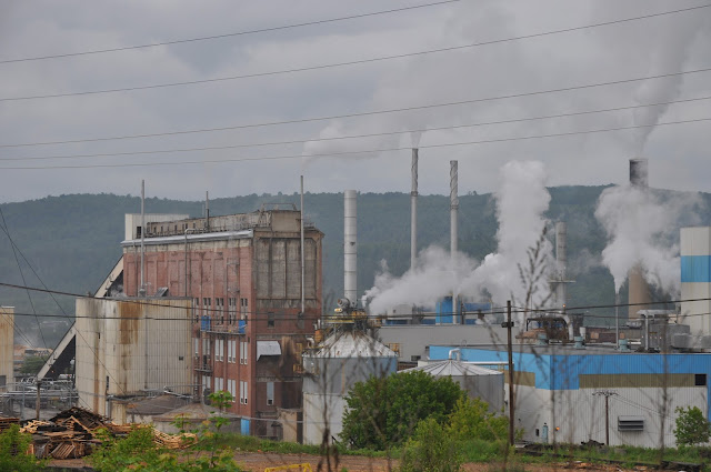
It goes without saying that modeling four operating plants takes up a large amount of space, which typically is not available with a model railroad regardless of which scale you're modeling.  However, I have used photos from the Kapuskasing and Temiscaming mills as backdrop, which is how I incorporate each of the mills.    

As I mentioned in Part 1, my Spruce Creek Pulp and Paper Mill is located on two 2’ by 6’ modules in the center of the room.  Starting from the left side, my buildings include a power plant, the pulp mill, alcohol plant, acid building, kaolin building, specialty cellulose mill, board mill and the warehouse.


High Yield Pulp - the pulp mill is a manufacturing facility that converts wood chips or other plant fibre source into a thick fibre board which can be shipped to a paper mill for further processing. Pulp can be manufactured using mechanical, semi-chemical or fully chemical methods (kraft and sulfite processes). The finished product may be either bleached or non-bleached, depending on the customer requirements.  In our mill, kraft pulp is produced using softwood pulp, while the "B" mill can produce either softwood or hardwood pulp.  Similar to the Boardmill, final products are shipped via both rail and truck.  The Kraft mill also produces large amounts of lignin liquor, a byproduct of the digestion process. This material can be shipped out in tankers, dried, or fed to other bacterias to make yeast.  The Kraft mill also uses other chemicals such as sodium hydroxide (caustic soda) and sulfuric acid. Kaolin (slurry form) is brought in to make glossy paper. Kaolin is often supplemented by calcium carbonate (lime) slurry and titanium dioxide.


The Chemical plant consists of products which are made from the spent sulphite liquor generated within the facility.  The plant can be divided into an alcohol division, resin division and lignin division.  Most of this operation takes place within numerous tanks situated within three central buildings.  Due to their relative size, I chose to model only the fronts of the buildings and blended the building into the photo backdrop.


Refined from wood pulp, specialty cellulose is used in a range of applications across many industries – cosmetics, pharmaceuticals, personal care, food, coatings, electronics and energy.  Specialty cellulose is manufactured in both rolls and bales.  Similar to the chemical plant, this area was modeled using only the front of the building set against the photo backdrop.


The Boardmill Division produces high quality paper and manufactures newsprint for publishers of daily newspapers and commercial printers, as well as controlled bulk paper for mass-market paperback book publishers and commercial printers.  Coated bleach board is a product used for a broad range of commercial printing, publishing and packaging applications.  Newsprint production uses wood fibre obtained from four separate sources, including thermomechanical pulp (TMP), recycled pulp, groundwood pulp and kraft pulp. 


Part 3 will look at the rail operations inside the mill.


Sunday, June 11, 2017

Passenger Service comes to the KLR

I have thought about adding an RDC to the KLR ever since they were first introduced by Rapido.  But I held to my original thought that the KLR was simply too small a railroad to have need of such equipment.  Well several weeks ago, after running on Bram Bailey's Ontario Central, I decided that I also needed at least one RDC.  Bram has three OCR units running on a regular passenger train route, and those Rapido's just run so nicely that after hearing them spool up to speed, I was hooked.
RDC 9051 picks up passengers at the Peterborough station.
After some Internet searching, I found someone in Indiana (of all places) selling a CP Rail RDC-1 at a decent price. The treasury of the KLR was able to come up with the money and the purchase was made.  The unit arrived this week, and after a little break-in session and some tweaking of the DCC system, everything was working and the RDC has been placed into service.  I'm still working on the details of its service, but for now it's going to function similar to what some of the RDCs used in British Columbia were used for.  That is the transport of school children and workers.  So until more details are worked through, the RDC will run in the early morning and late afternoon to transport everyone to Pembroke.  These will be whistle stops and all are welcome to flag down the unit for pickup.
RDC 9051 begins to pass over Eels Creek on it's way to Pembroke

Wednesday, January 18, 2017

First Operations in 2017

The first operations of 2017 occurred on the 2nd day of the new year and saw the KLR delivering some empty Thrall boxcars and woodchip gondola to the Muskoka Timber operations in Bracebridge, ON.  Plant workers finished loading the order the last day of the year onto the centerbeam flatcar, just before the New Year's holiday kicked into gear. By mid-morning Tuesday, workers were ready to load another flatcar with finished lumber and were eagerly awaiting the arrival of KLR 1646, which consisted of two empty thrall boxcars and an empty wood chip gondola.  The KLR made quick work of the pickup and drop and was headed back to the yard in time to catch some more holiday football games.
Dropping its van, KLR 1646 begins to move empty thrall boxcars onto the loading track

While a truck driver bringing in a new set of trees waits to unload, KLR 1646 inches past the boiler house.

Having dropper two thrall boxcars for loading, engine 1646 begins to back an empty woodchip gondola onto the chipper track

Thursday, April 28, 2016

Adding the Unimin Mine - Part 2

In a previous post, I described how I created the walls of the open pit mine as a background to my Unimin mining area, using a number of rock castings to portray the mined area.  This posting continues from that point, and I describe how the mine area was completed, using dyes to color the rocks and other materials to simulate the base of mining operations as well as blending the scene into the rest of the Unimin mine complex.


This photo shows the completed castings in place; gaps have been filled with spackle.  I added Sculptamold to the top of the hillside in order to smooth out the surface and give a slightly rounded top to the hillside, which will be planted with trees, bushes, etc as a final step.  While the top of the hillside was drying, I used dry wall compound or spackle to fill in any large joints which were present due to the castings pieces.  

Gray and white wash added to castings; top of hillside painted and ground foam applied.  I've also started to add the last wall in the bottom right of the photo.  I ran out of the pink foam board, and started to use some floral block in the upper right corner of the photo. Both are easily sculpted to the desired final shape.

Once everything was dry, it was time to get out the knives and start chipping away at the castings and spackle, to create the final shape of the rock face.  I've found that there really is no secret to this, unless you're trying to carefully follow a photograph.  I simply start changing the rock face by gouging the plaster, pulling deep cuts with my knife, until the shape takes on the appearance I'm looking for. Maybe this is where my geology background comes into play, as it's fairly easy to visualize the fissures, cracks, joints, etc in order to give the rock face a certain craggy look and feel.

For the mined road surface or bench, I simply added some spackle and dry plaster of paris onto the surface to complete it.  I don't want the surface to be perfectly smooth, rather the floor has to have the appearance of an area that has been mined but not so rough that trucks can't navigate on it.  Next come the difficult part, coloring the rock to the right color and consistency.

I like to use various colors of dyes to add color to the casting, rather than buying some of the commercially available liquid pigments.  The liquid pigments do a good job, however, you generally get one color per bottle and the bottles are about twice the price of available concentrated dyes.  I have found that Rit Dyes are inexpensive, come in a variety of base colors, and really set the color well in the plaster. One other advantage is that Rit has done some of the leg work for you, as their website provides a series of colors and what amounts of the colored dyes are needed to produce the final color.  I have colored many rock castings on the layout and still using my original bottle of Rit black dye after all this time.  I'm sure I would have gone through many bottles of liquid pigments rather than one.  Plus, I can easily make custom colors and if the results aren't to my liking, toss it without the feeling that I just used a good amount of the liquid pigment.  I mix my dye in a 70% rubbing alcohol solution.


I have a series of small, plastic screw-top containers that were bought at a discount store that hold approximately 2-oz of liquid and these are used to store my various color combinations. Before applying to the scene, I always like to test a small casting for the correct color content.  For example, to cast the plaster in a gray color, I have series of bottles ready, each with just a few more drops of black dye in them than their surrounding bottle, which allows me to darken the gray as necessary.  Remember to always start with the lightest color and work towards darker colors. 

Tools of the trade


Same area after several washes of gray have been applied.


Here's a photo after the initial "tan" dye has been applied.  It doesn't show well in the photograph, but the stark whiteness of the casting has been toned down and the plaster rock takes on the appearance of a more off-white color.

For the mine, I didn't want to add too much color to the castings, as the rock walls have a very light gray color to them when weathered, although they seem to take on more of a white hue on a fresh cut of the rock.   I always start with just a few drops of dye in the alcohol, progressively adding a few more drops of black dye to each bottle and testing each color before I apply it fully. 

Active mine area. Note that the rocks are a very light gray and in some locations appear to be white on a fresh cut of the rock face.


Here's the final version of the mine, although I need to undo some of the weathering I did as I'm not happy about some of the large "splotches" of gray or black in areas.

Monday, December 28, 2015

Adding the Unimin Mine (Nephton, Ontario) - Part 1

Geology 101 vs Model Railroading

I needed to take a break from the efforts of wiring, track work, etc on the paper mill modules before I tackled wiring the last island of the layout, so I decided to take a few days off and begin building my background for the Unimin mine area.  Unimin does open pit mining at its Blue Mountain facility, and while trying to model the open pit is impossible, I opted to model just a small portion of the mine, in the area where the mine trucks would be coming up and out from the mine.  While the area I have for the mine is fairly small and compressed, I really just wanted to give a sense of the mining operation and show trucks coming to the processing buildings.  As of summer 2015, the Blue Mountain open pit mine has been mined down to the 8th bench level, and mine officials project that there is at least another 25 years of ore remaining.
Blue Mountain Mine - Unimin
Initial base layer at the end of the new Unimin island of the layout
Now as someone who has a degree in Geology, I wanted the mine walls to show a level of creditability and really capture a rock face like you would see in an open pit.  Fortunately I was able to get some photos of the Blue Mountain pit and use them as a general guide.  However, I knew that I would be restricted in what I could model by both the areal size and vertical depth of the mine.  So my mine had to bend the physical reality a huge amount and have the haul road coming from only two bench levels, and telling visitors that the mine actually extends out into the aisle way.

So the first step involved cutting and attaching the base to the existing foam board. While I started with a 2" thick layer, I opted to cut that in half in order to have a rough surface.  The roadway cut into a 2" block also seemed to be out of perspective, so out came the cross saw and I carefully cut it in half.  Once this was done and glued to the base, it was time to start cutting the back pieces of foam to shape, gluing them together and then gluing them to the mine floor.  I tried to keep the same hillside profile by tracing the largest piece onto the smaller piece and then free handing the contour approximately 1" below the traced line.
Adding 3-D relief/base to the rock wall

Now comes the fun part, getting all those rock castings that I have made to fit into the designated spots, giving the impression of a hillside which has been actively mined yet still follows the fractures and joint patterns of the local igneous rocks of the mine.  While you can use large commercial castings, I prefer to cast rocks using a combination of commercially available molds and home made castings followed by large amounts of breaking castings into small pieces as well as cutting castings into small rock junks.  One of the keys to success is having enough rock castings available to you, as invariably you will find that your running out of castings or need a coasting that you already used for a certain space.  While casting is a relatively slow process, I have found that setting a number of "wet" castings onto a cookie sheet and baking them in the oven for about 60-90 minutes will greatly speed up the process. A "wet" casting is one where the casting has gone through the initial setup and can be removed from the mold, however, is far to wet to accept hot glue to place it on the layout. Of course, if you're going to dry castings in an oven, best to lay the "wet" castings on a piece of aluminum foil rather than upset your spouse by placing them directly onto the cookie sheet.

Fitting them against the hillside is done by the trial and error method.
Rock castings applied with hot glue
Before I actually glue them in place, I test fit them and then lay them aside until enough of the hillside is ready for gluing. Once the pieces are in place, you'll notice that you may have large gaps or cracks present.  The cracks may or may not require attention, as remember that rocks naturally have cracks or joints present as they have been altered by weathering and other processes.  Filling large gaps is easy enough, I simply mix some hydrocal into a fairly stiff mix (e.g. consistency like toothpaste) and force it into the spaces with my modeling or sculpting knife.  In many areas, I'll simply use my fingers to force the hydrocal into the gaps, making sure to get as little on the mold and obscure any details.  Since the molds are also made with hydrocal, there is no real difference in the coloring or how well the material will take the stain that we're going to use.  If you made your castings from plaster of paris, I'd suggest using the same materials too achieve that consistency.  One word of caution...try mixing small amounts of hydrocal, as the material sets fairly quickly (even when mixed with cold water) and working it into the gaps in a series of steps.  Too much materials mixed together will dry quickly, leaving you with firm hydrocal, which just has to be used as rock talus or thrown out.  For the area you see before you, I mixed 4 separate portions and applied them in small areas. After drying overnight, I'll come back with a knife and carve some additional fractures or alter the rock face to make it more blocky, giving the appearance of rock that has been blasted away or removed.
Upper rock face completed

Final result before adding the lower level and coloring the castings
The final step will be to add some additional Sculptamold to the top of the hillside, and add some tinting or coloring to the castings (to be covered in the next entry).

Thursday, November 26, 2015

System Map


When I began to develop the idea of modeling in southern to central Ontario, one of the key questions was what would a system map look like and how much area would I be able to realistically be able to cover in the space allotted me and keeping within my modular system.  My largest worry was that I would have no problems filling the layout with too many industries and not enough scenery, and that the layout would appear to have a very cramped feeling.

While my first ideas for a system map were actually drawn out on a Ontario Provincial road map, as Google has offered more services, I opted to convert my system map to an electronic version.  The system map has information embedded into each location, which supplements my KLR history, and allows a quick glance at prominent industries along the line.  I have also added the general ONR, CN and CP tracks as reference, and ultimately, more information about these lines will also be added.

Kawartha Lakes Railway System Map

Wednesday, July 15, 2015

ONRH&TS Convention Preview - Part 2

Pembroke is the home of several forest products businesses, including Commonwealth Plywood, MacMillan Bathurst Inc (corrugated containers), and Temple Inland(Medium Density Fibreboard). While not all of these industries are modeled due to space limitations, the KLR does service the Commonwealth Plywood facility. 

Here we see a few scenes from the downtown area as well as the siding for Commonwealth Plywood.

 True North Climbing Center & Sam's Bike Shop - named for my sons

Commonwealth Plywood

Royal Bank and RedTail Paddle Co.

ONRH&TS Convention Preview Part 1

I opted to preview parts of the layout for convention attendees.  Here's the first of the businesses found on the KLR.

Quaker Oats Company of Canada Limited- The Quaker Oatsplant in Peterborough produces cases of cereal and cake mixes at their facility. Raw materials, including various grains, oils, are transported to the facility by rail. It is quite common to see the yard filled with colorful grain hoppers of different sizes. Finished goods are transported by boxcar or truck.

A Beaver Lumber yard is also present in the town of Pembroke. I think that the old style Thrall all-door box cars were a really interesting design of rolling stock, so I took some modeling license and incorporated a business which could readily use this type of car to transport finished goods. 


Saturday, April 4, 2015

Kawartha Lakes Railway History

The Kawartha Lakes Railway is my HO scale freelance railway which incorporates certain elements of Ontario based industries and scenery into a fictional road.  The layout was designed to incorporate aspects of two of my favorite roads, the Ontario Northland Railway (ONR) as well as the Canadian Pacific Railway (CP Rail).  In essence, I have stretched the operating area of the ONR over into part of an area covered by the CP, as well as running track south to link with another area which the CP actually covers.  The railway is based on prototypical businesses found in the Peterborough/Lakefield region and well as several present in the Ottawa Valley. 

The setting is September 1985, as the summer comes to an end and the ever-changing weather of autumn descends upon the near north regions of Ontario. 

  
Throughout the KLR, I have tried to incorporate the history of the area into the areas that I model.  While certain key features or aspects couldn’t be modeled due to size constraints, I have tried to include enough key industries for realistic operations, without making the layout too busy. My goal was to mimic the remoteness of the area, having long runs between the yard and the various industries served.  Certain industries that are unique to the area have been included, as well as a few industries which are found in other portions of southern Ontario, but for the convenience of proto-freelance modeling, have been moved to fit onto the KLR. 

The primary purpose is to have the railway serve several small to medium sized industries located in the rural locales of Ontario.  The KLR's traffic base includes forestry products (such as paper, pulpboard, dimensional lumber and pulpwood) along with mining and several other industries.  The rail line serves a number of growing customers including Spruce Falls Pulp and Paper Company, Sherwin Williams Canada, Ontario Natural Products, Indusmin Canada, Ontario Hydro, Beaver Lumber .

The two largest industries on the layout include the Spruce Falls Pulp and Paper mill, which was modeled after the Tembec mills in Temiscaming, Quebec and Kapuskasing, Ontario.  The Unimin mine in Nephton, Ontario, which produces syenite (a mineral in the feldspar family used in glass making and ceramics), and the Muskoka Timber Ltd. operation serve as the other focal industries. The primary interchange is with the CP at Pembroke and Toronto (off the modeled layout), with a secondary interchange with the ONR at North Bay.  While CP discontinued trains east of Havelock and CN terminated its running line to Lakefield, the Kawartha Lakes Railway was able to purchase the trackage and become a profitable shortline, serving the small industries scattered throughout Ontario. 

The KLR was started in 2004, after the dismantling of a predecessor 9x12-ft oval layout. The layout is built using a series of modules, which generally follow the Freemo format.